CAD to PDF verification
5 Things to Verify Before Sending a Manufacturing Drawing PDF for Review
Your CAD drawing might be perfect. But is the PDF? Use these five checks before handing a drawing to a checker, supplier, or manufacturing engineer.
Published · 7 min read
Jump to the quick checklistManufacturing drawings are often created in CAD software, exported to PDF, and distributed for review, approval, or production. It’s a familiar workflow, but converting a CAD drawing into a PDF introduces another opportunity for errors.
Missing geometry, incorrect line weights, unreadable annotations, and outdated revisions can make their way into a drawing package even when the source drawing is correct. Once that PDF reaches a drawing checker, supplier, or manufacturing engineer, those problems can create confusion, unnecessary redlines, or incorrect manufacturing decisions.
Before sending your next manufacturing drawing PDF for review, take a few minutes to verify these five things. The checks apply regardless of which CAD system or PDF editor you use.
1. Make Sure All Drawing Geometry Exported Correctly
Does the PDF actually show everything that appears in the CAD drawing? Depending on your CAD software, export settings, and drawing complexity, some geometry may appear differently in the PDF.
Look for:
- Missing or partially displayed edges and cropped drawing views
- Hidden lines or tangent edges appearing incorrectly
- Centerlines or center marks disappearing
- Section views losing important detail
- Drawing views appearing at unexpectedly low resolution
What to check
Open the exported PDF and compare it against the original CAD drawing. Pay particular attention to section views, detail views, complex assemblies, and features near drawing-view boundaries.
Zoom into small geometry and fine linework; a full-sheet view can hide export problems. If a view looks unusually pixelated or simplified, check whether the CAD export preserved vector geometry or substituted a lower-quality representation.
A manufacturing drawing PDF should communicate the same geometry as the source drawing.
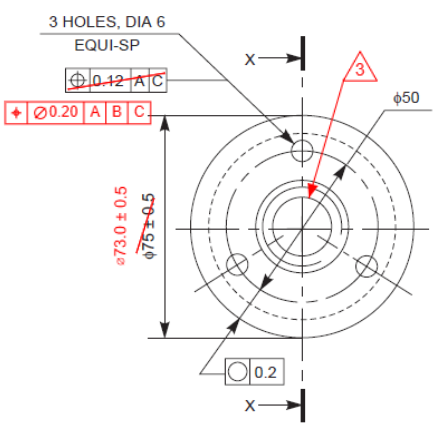
2. Verify Dimensions, Tolerances, and GD&T Symbols
Dimensions and tolerances are among the most critical pieces of information on a manufacturing drawing. An export issue that affects a tolerance or datum reference can change how a requirement is interpreted.
Look specifically for:
- Missing dimension values or truncated dimensions and extension lines
- Incorrectly rendered diameter, degree, or plus/minus symbols
- Superscripts and subscripts displaying incorrectly
- GD&T feature control frames with missing or substituted symbols
- Datum identifiers that are difficult to read
- Tolerance values overlapping nearby geometry
Font substitution can be a particular concern when drawings use specialized engineering fonts or symbols.
What to check
Zoom into representative dimensions and GD&T callouts and compare their displayed values and symbols with the original CAD drawing. Inspect every critical dimension, tight tolerance, and complex feature control frame rather than relying on a few samples.
Don’t assume the PDF is correct simply because the overall drawing looks familiar. A single missing symbol can change the meaning of a manufacturing requirement.
3. Check Line Weights, Text, and Overall Readability
A drawing can contain all the correct information and still be difficult to interpret. Line weights, font sizes, and visual hierarchy help communicate engineering intent.
Visible edges should be distinguishable from hidden lines, centerlines, dimension lines, and section hatching. If every line appears at the same thickness, the drawing becomes harder to read. Text that looks fine in CAD may also become difficult to read when exported or printed.
Common issues include:
- Dimension lines appearing too thick or thin geometry disappearing when printed
- Section hatching overwhelming nearby details
- Notes becoming too small to read or text overlapping geometry
- Incorrect font substitution
- Poor distinction between different line types
What to check
Review the drawing at both full-sheet and detail-level zoom. If it will be printed, check a print at the intended paper size. For large-format drawings, also consider how the information will appear if recipients use smaller paper.
Verify that notes, dimensions, and symbols remain legible in the formats your team actually uses, whether that’s a large engineering monitor, a laptop, or a printed sheet on the shop floor.
4. Verify the Drawing Revision and Title Block
Even a perfectly exported drawing can create problems if it’s the wrong revision. Before distributing a manufacturing drawing PDF, verify its identification and revision information.
- Drawing number and title
- Revision identifier and revision history
- Sheet number and total sheet count
- Material specifications, general tolerances, and units
- Applicable drawing notes
- Approval and release information, where required
For multi-sheet packages, verify that every sheet belongs to the intended drawing set and matches its controlled revision record. It’s easy to combine a newly exported sheet with an older PDF from a previous revision. Confirm that the filename and document-management metadata align with the drawing’s actual revision.
What to check
Compare the exported PDF against the authoritative drawing record in your CAD, PDM, or PLM system. If it is part of an engineering change, confirm that the correct revision was exported and all required sheets are included.
The PDF filename alone should never be treated as proof of revision status.
5. Open the PDF Independently Before Sending It
Open the exported PDF in a separate PDF viewer and inspect it as the recipient will. Don’t rely exclusively on the preview inside your CAD application; an independent viewer can help reveal display or compatibility problems that aren’t obvious during export.
- Open the exported PDF in your normal drawing review application.
- Verify that every sheet opens correctly.
- Zoom into several complex drawing regions.
- Check dimensions, GD&T, notes, and symbols.
- Confirm the drawing revision and sheet count.
- If appropriate, open the file in a second PDF viewer to check compatibility.
- Verify that the file is readable and ready for the intended review process.
If you’re sending the PDF to a supplier or customer, check their requirements for file format, document naming, security, and drawing presentation. A file that works on your computer isn’t guaranteed to display identically in every environment.
A Quick Manufacturing Drawing PDF Checklist
Before sending your next drawing for review, run through these five checks:
Use the boxes as a quick check during this visit; selections aren’t saved.
These checks add a verification step to help ensure the PDF accurately communicates the intended drawing information. They don’t replace a formal engineering drawing review or your organization’s document-control procedures.
For the engineering review itself, continue with our mechanical drawing review checklist.
Review Manufacturing Drawings With PDF Engineer
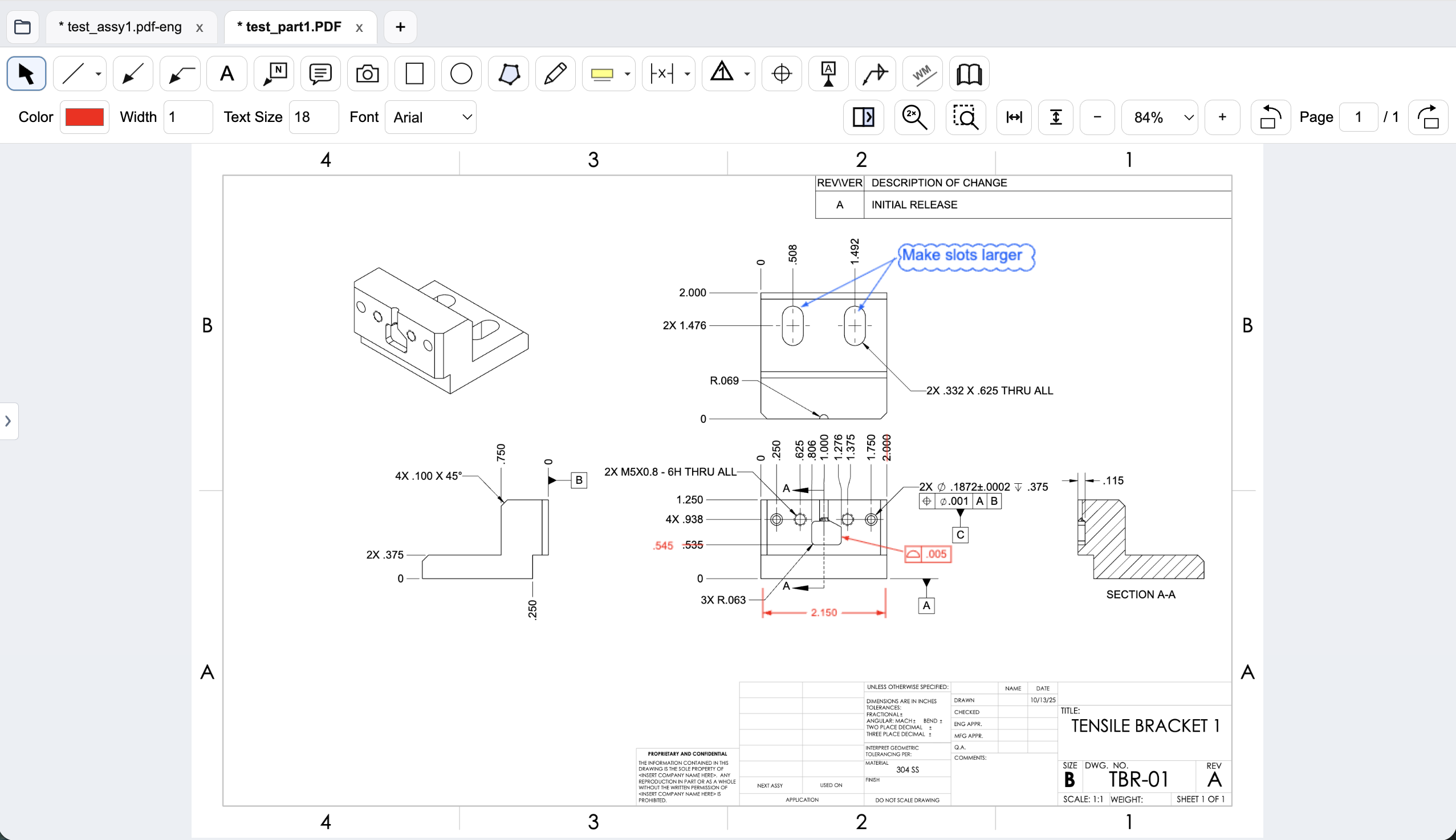
Once your PDF is ready for review, the next step is communicating drawing changes clearly. PDF Engineer is a Windows desktop PDF editor designed specifically for mechanical engineering drawing reviews.
Engineers can create purpose-built redlines, including:
- GD&T feature control frames
- Dimension annotations
- BOM balloons and flag notes
- Weld symbols
- Lines, arrows, centerlines, and other mechanical markups
PDF Engineer processes drawing contents locally, without uploading them to PDF Engineer’s servers for rendering, review, markup, or export. Read more about local document processing.
Whether you’re checking a new design, reviewing a supplier drawing, or communicating changes to a designer, the tools are built to help you place clear engineering feedback directly on the drawing.
If your team is evaluating software, see 7 Things Engineering Teams Should Check Before Adopting a New PDF Editor for a broader look at compatibility, security, licensing, and deployment.
Check the PDF Before the Review Begins
A manufacturing drawing isn’t ready for review just because it exported successfully. The PDF itself needs to be checked.
A few minutes spent verifying geometry, dimensions, readability, revision information, and file compatibility can prevent unnecessary confusion later. Your drawing is only as useful as the information the recipient can actually see and understand.